Electrical Resistance Testers – Keeping an Eye on Insulators
Electrical resistance is as important as conductivity as it provides a safety measure for electrical systems. One such component made to prevent electricity from passing through is an insulator. Insulators are materials such as plastic, glass, rubber and dry wood – they let no useful current flow through when voltage is applied.
Useful current means more than 1 microampere. This is not to be confused with resistors though as the electrical resistance of a resistor is much lower than that of an insulator. But why do insulators need to be tested? In case a tiny amount of current flows through an insulator, it needs to be detected so further consequences are prevented.

What Is a Megohmmeter?
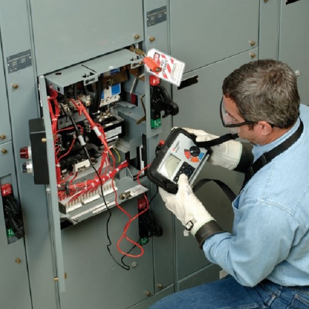
When it comes to testing insulators, this is the device for the job. An insulation resistance tester or what is also known as a megohmmeter is another type of ohmmeter used to check if insulators are effective or not. They are basically an ohmmeter with a large capacity capable of generating DC current from its battery.
How to Use a Megohmmeter?
How It Works
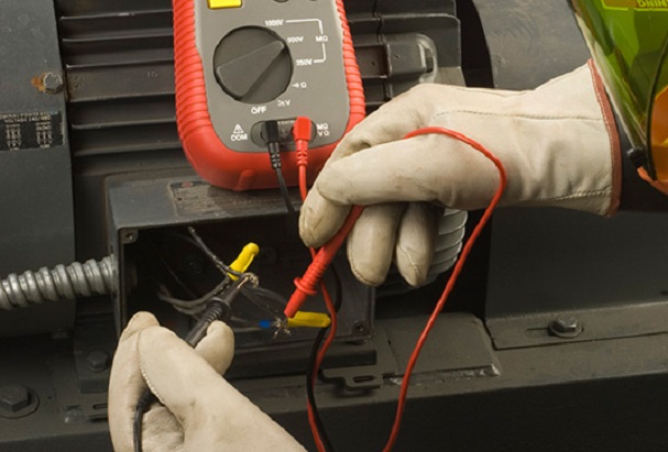
In order to learn how to use a megohmmeter, you first need to understand how it works. This device produces a DC current with a certain voltage, depending on the type of insulator, using either a hand-cranked small internal generator or an internal motor. The DC current generated by the device will make a small amount of current flow through the conductor and then what follows is insulation. The sum of the insulation resistance is a value consisting of three independent sub currents.
The first is called conductive leakage current which is a small amount of current that usually passes through the insulation. This is the most important current since it’s time dependent and also fairly steady. The second sub current is called capacitive charging leakage current which flows as a result of a capacitive effect generated by two or more conductors running parallel to each other. Polarisation absorption leakage current is the result of polarisation in molecules within dielectric materials.
Methods
The simplest test and one that is the core of insulation resistance testers is, you guessed it, insulation resistance (IR). This is a test with a short duration as it requires voltage to be applied for about a minute. This test is temperature sensitive – when the temperature goes down, IR goes up and vice versa.
Step voltage test is resistance testing done at various voltage settings. This test involves a test voltage being applied for about a minute which is increased over time. If the insulation is in a good state, the resistance value will stay about the same when increasing the voltage, otherwise there will be an increase in current flow especially at high voltages. If the test shows a drop in resistance values above 25% it means that the insulation is damaged and degraded.
The dielectric adsorption test which is also known as the time-resistance test works by comparing the insulation characteristics of a contaminated insulation to those of a good insulation. The test is performed by applying test voltage over a ten minute period whilst recording the results at regular intervals. All the results are shown in the form of a graph. If the curve is continuously going upwards, it means that the insulation is good but if there is a flat or a curve going downwards, this is an indicator of either cracked or contaminated insulation.
Safety Tips
When doing any of the above tests, it’s important to have all the equipment that’s going to be tested disconnected and properly isolated. The equipment should also be discharged (shorted out) beforehand for at least the amount of time it takes to perform the test. Make sure that all connections in the circuit are tight before you start testing. Have all the switches blocked out and cable ends marked properly.
Cable ends that need to be isolated should be disconnected from the supply and they should not get in contact with the ground or power supply at any given time during the test. Safety barriers together with warning signs should be positioned and you should have an open channel for communication with the rest of your testing personnel. When testing for earth, always have the far end of the conductor safe from getting in contact with the ground as the test will show a fault in the insulation when there isn’t any.
When testing high insulation measurements, in addition to following the above mentioned safety tips, make sure you use the guard terminal. Also, ensure that the leads are dry and clean. Always set up the leads with a safe distance from one another and make sure they are not in contact with the floor or any other object in order to prevent leakage current. Avoid touching or moving the leads during the test to prevent disturbances which are going to be generated due to capacitive effects. When doing high insulation spot measurements, make sure you wait out the time needed for stabilisation.
 The Sound of Tradition: An In-Depth Look at the Fender Telecaster Series
In the realm of electric guitars, few instruments hold...
- April 16, 2024
 Professional and Stylish: How to Select the Right Men’s Uniform for Your Business
What kind of picture do you want to present...
- April 9, 2024
 Warehouse Organisation: The Role of Stillages in Streamlining Operations
If you’re a business owner who deals with goods,...
- April 8, 2024
 5 Thoughtful and Practical Gifts for New Parents
Welcoming a new baby into the world is an...
- March 29, 2024
 Wood Fired vs Gas Pizza Ovens: Which One Should You Get?
If you love pizza, then owning an oven designed...
- March 26, 2024
 Beyond the Bars: A Guide to Choosing the Right Cat Cage
Sharing your life with a furry friend is a...
- March 22, 2024